
A substation battery is judged on a duty it performs perhaps once a year, for a few minutes, in the dark. For the rest of its life it floats silently on the DC bus, doing almost nothing — and then the grid fails, and everything in the building that still has to work works because of it. Protection relays must see the fault. Trip coils must open the breakers. Breaker motors must recharge their springs. SCADA must keep talking to the control centre, and the emergency lights must stay on until supply returns. The US Bureau of Reclamation’s battery manual puts it in one sentence: the DC system is “usually the last source of reliable electrical power at a facility”. The engineering discipline that turns that sentence into a cell count is the duty cycle, and it is the least understood line on any substation battery specification. This guide explains what it is, how a bank is sized against it, and why the sizing has to be done for the battery’s last year rather than its first.
What a duty cycle actually is
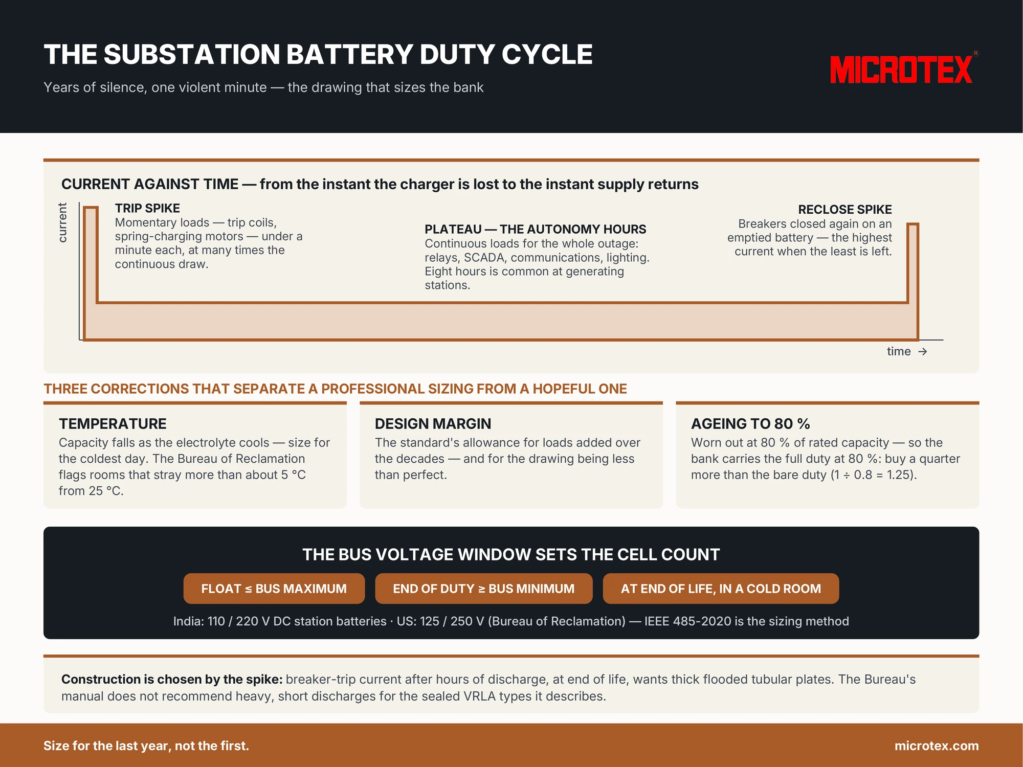
A duty cycle is a drawing before it is a calculation: current on the vertical axis, time on the horizontal, from the instant the charger is lost to the instant it returns. The recommended practice the world sizes stationary batteries by — IEEE 485, currently in its 2020 edition — divides that drawing into periods and sorts every load in it into three kinds. Continuous loads run for the whole outage: relays, indication, SCADA, communications, lighting. Momentary loads are the violent ones — a trip coil, a breaker spring-charging motor, a bank of breakers opening together — each lasting under a minute, sometimes under a second, at currents many times the continuous draw. Intermittent loads come and go somewhere between the two. A typical substation drawing therefore looks like a low, flat plateau of hours with a jagged spike at the very beginning, when the fault clears and the breakers trip, and often another spike at the very end, when supply returns and breakers are closed again against a battery that is already emptied. That last spike is the one that catches designers out: the battery must deliver its highest current at the moment it has the least left to give.
The bus voltage window: the constraint that sets the cell count
Ampere-hours are not the first thing a substation battery is sized for; voltage is. Every relay, coil and motor on the DC bus has a minimum voltage below which it will not operate, and a maximum above which it may be damaged. Indian utility practice runs station batteries at 110 or 220 V DC; the Bureau of Reclamation records US station service at 125 and 250 V, with 48 and 24 V systems reserved for instrumentation and communications. Whatever the nominal figure, the bank has two hard limits: on float the bus must not exceed the equipment maximum, and at the end of the duty cycle — after the hours of plateau and the final spike, at the room’s real temperature, with the cells at end of life — the bus must not fall below the equipment minimum. Those two limits fix the number of cells, not habit or catalogue. As our substation battery page puts it, the count follows from your voltage window; give the two limits and the count falls out. Our series and parallel guide covers the string arithmetic, and our guide to DC earth faults explains the other defining feature of this bus — that it deliberately floats free of earth so that a single fault alarms rather than trips.
Sizing for the last year, not the first
With the drawing and the voltage window in hand, the sizing works period by period: for each section of the duty cycle the method asks how much capacity the load consumes and which section is the hardest, and then it applies three corrections that separate a professional sizing from a hopeful one. The first is temperature: lead-acid capacity falls as the electrolyte cools, so a bank in an unheated room is sized for the coldest day, not the datasheet’s reference — our guide to operating temperature explains why the Bureau’s manual calls for special design consideration when a battery room strays more than about five degrees from 25 °C. The second is a design margin — the standard’s allowance for loads that will be added over the decades and for the drawing being less than perfect. The third, and the one most often skipped, is ageing. The industry convention is that a battery is worn out at 80 percent of rated capacity, and a bank that will only carry the duty when new is a bank that fails its purpose for most of its life. So the bank is sized to carry the full duty cycle at 80 percent — which, as plain arithmetic, means buying a quarter more capacity than the bare duty demands (1 ÷ 0.8 = 1.25). The 2014 Battcon paper by Searles and Schiemann states the expectation exactly: when a battery is sized by IEEE 485 it is “customary to expect that the battery will handle the defined/required duty cycle” down to that 80 percent end point. Our battery sizing guide gives the general five-step chain; the substation version is that chain with a jagged drawing at the front and an ageing factor at the back.
Autonomy, and why the construction is chosen by the spike
Two decisions remain. Autonomy is how long the plateau must last with the charger dead — the Bureau notes that an eight-hour backup time is often used at generating facilities, and each utility’s planning standard sets its own; the honest specification states the hours and the load, not just the hours. Construction is chosen by the spike. A battery that must deliver a breaker-trip current after hours of discharge, at end of life, in a cold room, wants thick, robust plates that hold their voltage under a hard pull — which is why utilities with trained crews specify flooded tubular cells for this duty, and why the Bureau’s manual states plainly that heavy, short discharges of the kind breaker operation demands are “not recommended” for the sealed VRLA types it describes, which it reserves for long, slow duties such as lighting and telecommunications. It is also why a substation bank is nearly always single two-volt cells rather than monoblocs — every cell readable and replaceable on its own, the argument our cells-versus-monobloc guide makes in full. One more detail from the same manual tells you how seriously this bus is taken: breakers and fuses are typically not fitted on the main DC bus at all, only on the branch circuits, because a main protective device that could open is a reliability risk greater than the fault it guards against.
Proving the drawing was right
A duty cycle is a hypothesis about the worst day, and hypotheses get tested. The proof is a discharge test against the actual drawing — the plateau load for the autonomy period with the momentary loads applied at the right moments — with the bus voltage logged throughout and compared against the equipment minimum; our guide to testing a battery explains why this, and only this, counts as evidence. Between tests, the bank spends its years on float, and the discipline that keeps the drawing true is unglamorous: hold the float, keep the room near its design temperature, water on schedule, and read every cell on the round — our maintenance walk-round sets it out, and the black-start guide shows what the same discipline looks like when the duty is restarting a grid rather than protecting a substation. If you are writing a substation battery specification now, the seven lines that matter are on our product page; if you already have a single-line diagram and a load list, send them — we draw the duty cycle, size the bank to your voltage window at end of life, and return the arithmetic with the quotation so that you can check it.
Sources quoted: U.S. Bureau of Reclamation, FIST Volume 3-6: Storage Battery Maintenance and Principles (April 2020); C. Searles and M. Schiemann, “Understanding and Differentiating Design Life, Service Life, Warranty and Accelerated Life Testing for Lead Acid Batteries”, Battcon 2014.